In the previous article in the September 2018 issue of World Grain, the procedure to measure break release was presented as part of a series of articles to discuss in greater detail the development and utilization of the three tools mentioned in Mark Fowler’s article, “Balancing the mill,” in the February 2012 issue of World Grain.
John Wingfield, in the “Dictionary of Milling Terms” published by the International Association of Operative Millers in 1989, defines mill balance as “the proper distribution of stock to the various parts of the milling system, as determined by the flow sheet, to ensure proper loading of equipment and high milling efficiencies.”
Wingfield suggests that the distribution or balance of the ground stock must be kept within the parameters of the system design to maximize mill performance as part of the balancing act measures. The expected distribution of ground stock can be estimated or predicted by utilizing a granulation curve. The granulation curve builds upon knowledge revealed by measuring break release in that it further describes the particle size distribution of the released material.
Factors impacting the granulation curve
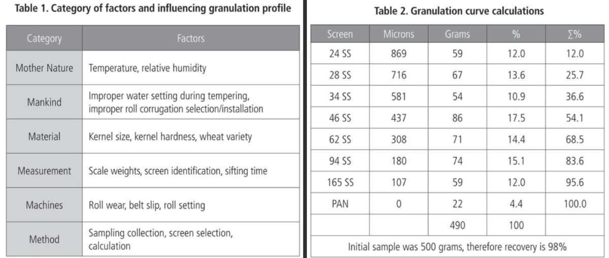
Mill balance and product distribution variability is endemic to any processing system and performance measures. In reviewing six categories — Mother Nature, Mankind, Materials, Method, Measurement and Machines — some factors that influence granulation profile variations are identified in Table 1.
Definition: A granulation curve or profile curve is a graphic representation of the measured percentage of cumulative material held over a given size screen opening. The granulation curve can be used to estimate expected loads to various processing points in the flow, evaluate roll wear, evaluate sifter efficiency and predict or estimate loading changes due to alternative screen selection via visual inspection or linear interpolation.
Sampling: As with break release sampling, samples collected for sifting analysis must be representative of the material being evaluated. It is important that a complete cross section of product flow be collected, especially where particle segregation may occur due to particle size or composition such as in spouting where stocks from various sources may be combined. No matter the device or method used, one is encouraged to look at sample collection methods and procedures to minimize variation in sample uniformity, including sample size.
A sample size of 100 to 500 grams to be sieved on a test sifter with a 530 to 930 square-centimeter surface should be appropriate, but keep the sample size uniform for a given study. Sieve height, sieve area and stock density determine sample quantity allowed to provide for free-flowing action. The pan, just like the sieves, must hold fines removed without allowing them to push up through the screen above. Use of the entire sample is suggested due to the potential of segregation of sample in handling and potential to discard material that would alter the representative nature of the sample collected. It is rather unlikely that one could dispose of a portion of a sample without disturbing its representative nature.
The stock must move freely on the screen surface. Sifting times may range from one to five minutes; coarse screen openings require less time, while fine screens, such as flour cloth, require more time.
The end point is reached when less than 1% additional fines are removed. Do not use excessive sifting time as it may “create” additional small particles than exists in the sample. Cleaners are needed if the bare screen appears blocked and lighter colored material is surrounded by darker, more granular material on the surface of any given screen.
Clothing Size: Clothing size selected for measurement include an appropriate range of openings reflected in the flow sheet and intermediate sizes to improve interpolation accuracy for proposed alternative screen sizes. Breaks stock can generally be evaluated on screen sizes of 0.125 to 4 mm with semolina granulation measured between .125 to 1.12 mm and middlings reduction or C1-CX granulation between 0.075 to 0.375 mm. The size spread between sieves should be minimal if the data is to be used to develop granulation curves to evaluate proposed clothing changes in the milling process. Sieve frames are stacked with finest openings at the bottom above the pan and increasing size limited by the test sifter frame capacity.
Sifter Motion and Time: The test sifter should have throw (diameter of gyration) and speed (RPM) like that of the mill sifters. Appropriate sifting time can be identified by sifting in 10-second increments and determining when less than a 1% change in through stock based on the original sample weight has been identified with the sample screen remaining clear and no fines observed in the over tail.
Finer materials sieved on smaller screens may require longer sample sifting times to achieve the endpoint and provide meaningful measurement. In some cases, a sieve cloth cleaner or other cleaning device positioned on screen as well as held on a back wire below the screen may be necessary to obtain a meaningful and repeatable performance measure.

Developing the Granulation Curve: The initial sample weight is carefully recorded and the sifter operated for the time needed to complete the sifting process. The weight of each fraction held on the screens and in the pan is carefully measured and recorded.
The sum of individual weights or recovery should be at least 95% of the initial sample weight for the test to be meaningful (98% preferred). If the recovery is less than 95%, a new sample should be obtained and the test re-run. Once sample recovery is determined to be adequate, calculate the percentage held on each screen based on the total recovered sample weight. Then, starting with the coarsest screen, add the percentage held over to the next smaller screen fraction percentage until the pan has been included and the cumulative percent held over the pan is 100%.
An example of a test and calculations are provided in Table 2. The data to be plotted on a scatter plot will be the screen size held over on the “X” axis with the corresponding Percent Held Over on the “Y” axis. Note that percent (%) and cumulative percent (∑%) can be replaced by proportion and cumulative proportion, respectively.
Utilization of Granulation Curve: The percent held over a given screen is the difference between the cumulative percent held over that screen and the specified larger screen. For example, the percent of material over the 581 but through the 716 μm screen is 10.9% as shown in Table 2 (36.6-25.7=10.9) or estimated from the graphic. A visual estimate for any point along the curve is made by drawing a vertical line from the opening size desired until it intersects the granulation curve. From the intersection, one draws a line horizontally to the “Y” axis to determine the cumulative percent of material held over the desired opening.
Let’s look at an example where material over the 869 μm screen goes to the next Break Roll and material through the 869 μm screen, but held over a 437 μm screen, is sent to Purifier 1, and material through the 437 μm screen, but held over the 308 μm screen, is directed toward Grader sifter. Suppose then a miller felt that the 869 μm screen should be changed to an 800 μm screen and the 437 μm screen would be changed to a 400 μm screen. The question is: What happens to the load to the Break Roll, Purifier 1 and material to the Grader sifter section sifting material over a 308 μm screen?
Graphically, it looks like Figure 1 where the estimated cumulative percentage held over the 800 μm screen appears to be 18%, the estimated cumulative percentage held on the 400 μm screen appears to be 58%, while the cumulative percent held over the 308 μm screen remains 71% as shown in Table 2.
The load to the Break Roll increases from 12% to 18%, a 50% increase in load. The load to Purifier 1 decreases from 42.1% (54.1-12.0=42.1) to 40%, (58-18=40) approximately a 5% load reduction, and the load to the Grader changes from 14.4% (68.5-54.1=14.4) to 3.9% (58.0-54.1=3.9), approximately 73% load reduction.
Now that the load change has been determined, the miller must determine if the equipment can handle the increased or decreased loading or if other adjustments will be required to maintain product quality. This is where the milling knowledge comes into play.
Mathematical interpolation can be used if desired but is not always necessary if the graph developed is large enough for visual determination. To mathematically calculate the cumulative percent over the 800 μm screen we can use the data shown in Table 2. The 800 μm screen lies between two known points, namely the cumulative percent held over the 869 μm screen (12%) and the 716 μm screen (25.7%) for a difference of 13.7% (Table 2 shows 13.6% due to rounding). The difference in opening size is 153 μms.
From this we calculate the slope of the graph, which is change in cumulative percent held over per change in screen size opening between the two known points (13.7/153=0.089542). Since our target screen opening has changed by 69 μm (869-800), we can multiply the change in μm size opening times the slope and add the product to the cumulative percent material known to be held over the 869 μm screen to obtain the cumulative percent held over the 800 μm screen. In this case the interpolated cumulative percent held over the 800-μm size screen is 18.17% ((0.089542*69) + 12=18.17)
Granulation Curve/Profile Discussion: Development of granulation profile development is a repeatable process, presenting replications of 10 First Break Granulation curves (see Figure 2A). Granulation curves for First Break given different wheat hardness index can show how mill balance and distribution can be affected by kernel hardness (see Figure 2B). The granulation profile of fine materials not identified by a break release rest provides insight to shifting mill balance and purifier loading changes.
Conclusion
Break release measurement gets you into the right ballpark for proper mill balance while the granulation curve combined with good milling knowledge gets you one step closer to mill optimization. Perhaps measures of in-process granulation curves/profiles can help to improve mill operations in terms of reduced variability and optimal mill balance improving extraction and quality.
