In my last two articles, I looked at the ingredients and quantities to be weighed in the batching scale for two different formulas — one for a broiler feed and the second for a swine feed that were introduced in previous articles. The target time was determined for weighing the necessary ingredients in each formula to meet the required design production capacity for the mill.
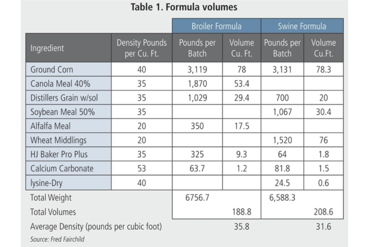
In this article, I will look at the volumes required and how to design the scale hopper and its discharge gate. I also will determine the size of the mixer needed. Table 1 uses the amount and density of the materials to determine the volume of mixture for each formula to be weighed and mixed in the system.
The table shows that although the total weight of each of the formulas is relatively close, the volume of the two batches varies significantly. This difference is due to the variation in ingredients used in each formula and the density of each ingredient.
Scale hopper gate sizing
As Table 1 shows, a batch of the swine formula requires the greater batch volume of 208.6 cubic feet. In a previous article, we assumed that the scale hopper should empty in no more than 10 seconds.
In my design for gates under bins or hoppers for meal type product, I use a factor of 50 cubic feet per hour per square inch of gate area needed. This figure normally works well, but the product to be handled through the gate and its flowability must be considered.
The slope of the hopper must be considered. Using 208.6 cubic feet to be discharged in 10 seconds, we calculate the cubic feet per hour needed. 208.6 CFH/10 seconds per dump times 3,600 seconds/hour = 75,096 CFH capacity. Divide 75,096/50 = 1,502 square inches of gate area needed. Calculating the square root of 1,502 square inches, the gate size is calculated to be 39 inches by 39 inches. We actually will use a 40-inch by 40-inch gate for this design as it is a more common size. This should be a quick opening and closing gate.
Additionally, the gate should have a sealed enclosure, including a 50- to 60-degree sloped hopper under the area where the open gate retracts to. This will allow any material blown into the gate recess area to slide down into the mixer when unloading the scale.
Scale hopper design and sizing
For the scale hopper design, I use twice the actual volume needed. This is because the screw feeder outlets cannot all empty into the scale at the center of the top cover. Thus, most enter the scale off-center in the top. Room needs to be provided so that each ingredient can fully enter the scale and not be backed up into the feeder due to the volume and angle of repose of each ingredient.
If all ingredients cannot be fully placed in the scale hopper, inaccurate scale readings can occur due to ingredients not getting into the scale hopper or pressure being put on an ingredient from its feeder.
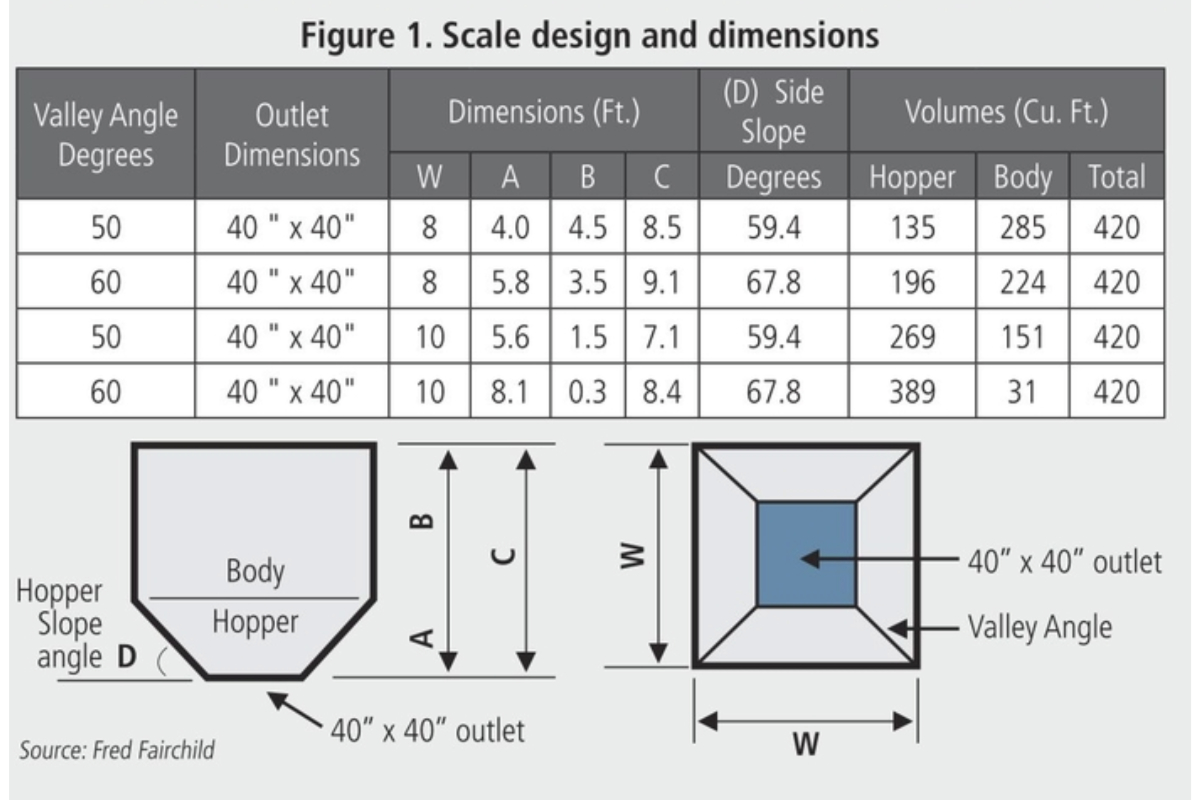
For this design we will demonstrate two square-shaped scale hopper designs with an 8-feet by 8-feet or 10-feet by 10-feet body dimension with a centered 40-inch by 40-inch outlet. The two different hoppers also will be designed using 50-degree and 60-degree valley angles where two sides meet. This meeting of the two sloped sides is called a valley angle. This valley is the critical slope for the hopper.
To attain a 50-degree slope in the valley, the two sides of the hopper forming the valley are steeper than 50 degrees. Likewise, for a 60-degree valley slope, the hopper side slopes are greater than 60 degrees. The total scale volume for design will be 210 cubic feet times 2 = 420 cubic feet.
Figure 1 shows information and dimensions of the hoppers and bodies that might be used to build hoppers of this capacity. The formula for determining the volume of the hopper section is readily available on the internet. Also, look for pit volume calculators. The hopper is actually an upside-down pyramid with the top cut off. The mathematical term for this shape is called a “frustum.”
The scale has a fixed top cover that is attached to the scale hopper with a flexible connector such as canvas or rubber. Likewise, the outlet of the hopper gate is connected to the mixer with an additional flexible connection. The scale itself is mounted on loadcells that send a signal to the scale reader indicating the weight of the scale assembly and any product in the scale.
The weight of the scale assembly is a fixed weight that can be tarred out (deducted) so only the weight of any materials in the hopper are shown on the scale readout.
Choosing a mixer
Most often, you will hear the capacity of a mixer referred to in tons capacity. Actually, a mixer is a volumetric machine and the size is based on its cubic feet of useable capacity. With the formulas we are making in this article, the mixer needs to be able to handle the swine volume of about 210 cubic feet. The mixer must have the power to handle the density of the formulas to be mixed. It also needs sufficient power to handle both dry mixing and mixing the same formula when liquid ingredients are added. The mixer should be of a twin rotor type so batches of lesser volume may be thoroughly mixed.
Using the target times for the feeders to fill the scale, the mixer must be able to thoroughly mix the dry ingredients and then the addition of liquids added to the formula while mixing. This means that the mixer needs to be able to mix the dry ingredient in less than a minute to allow time for the liquid ingredients to be added and fully mixed into the formula.
The mixer should also be equipped with a fully opening bottom to quickly dump the mixed batch into a surge bin below large enough to hold the dumped materials beneath the mixer doors so they can be quickly closed for receiving and mixing the next batch.
System Inter-Venting
The scale top, mixer top and surge bin below the mixer are tied together in a venting system to handle the air volume displaced when a formula is dumped from the scale hopper into the mixer or from the mixer into the lower surge bin. This venting system should be sized so the air velocity in it doesn’t exceed 500 feet per minute. At this velocity, most of the ingredients don’t flow well and remain in the equipment receiving the batch.
Additionally, I recommend a small open-bottom bag house filter be installed on the scale top to relieve any air pressure problems while scaling the ingredients. I know of a few cases where the conveyor emptying a batch from the lower surge into a bucket elevator carried back pressure from the bucket elevator into the surge and inter-venting system that caused the scale to rock on its loadcell supports and cause inaccurate weighing. This also was solved by adding the small baghouse filter on the scale cover.
Small inclusion ingredients in each formula are added using a separate micro-ingredient system. This system is a small scaling and batching system that discharges into the mixer during the dry mixing time for the mixer.
In my next article, I will discuss liquid ingredient systems and liquid addition at the mixer and other locations.